Calculate Ratiometric Single Pair FRET Distributions Using PIE-FRET
Summary
This tutorial shows step-by-step, how to calculate a FRET histogram from single FRETpairs detected under single molecule conditions using pulsed interleaved excitation (PIE). The script requires a spectrally resolved fluorescence time trace, in which donor and acceptor have been excited alternately. As a result, the distribution of FRET efficiencies of different molecules is shown which can be used to detect subpopulations.
Note: The script requires a time trace containing the fluorescence of two spectrally separated channels, one channel mainly detecting the fluorescence of the donor dye and the other channel detecting mainly the fluorescence of the acceptor dye.
The time traces can be acquired from single molecule events in a diluted solution, where the passages of single molecules are registered as “bursts”. Alternatively, traces obtained from a stationary single FRET pair can be analyzed, e.g. to observe conformational changes.
To record such traces, usually single molecule sensitive detectors as SPAD or Hybrid PMTs are necessary to successfully detect single molecule fluorescence.
For the pulsed interleaved excitation (PIE) analysis of the script, pulsed excitation using two lasers is required, one laser exciting the donor, the other the acceptor dye. Usually, this is achieved using the multichannel laser driver PDL828 “Sepia II” in combination with two pulsed diode lasers.
Step-by-Step Tutorial
Select a file and start the script
- Start SymPhoTime 64 software.
- Open the “Samples” workspace via “File\open Workspace” from the main menu.
Note: The “Samples” workspace is delivered with the SymPhoTime 64 on a DVD-ROM and contains example data to show the function of the SymPhoTime data analysis. If you haven't installed it on your computer, copy it from the DVD onto a local drive before going through this tutorial.
Response: The files of the sample workspace are displayed in the workspace panel on the left side of the main window.
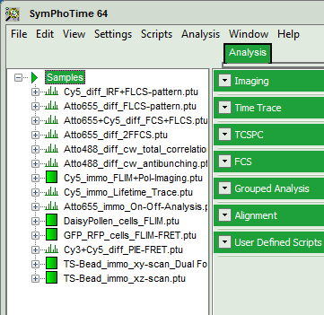
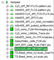
- Highlight the file
Cy3+Cy5_diff_PIE-FRET.ptuby a single mouse click.
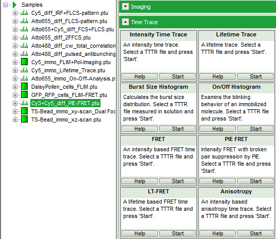
- Select the “Analysis” tab and in there, open the dropdown menu “TimeTrace”.
Note: The drop down menu can be opened and closed by clicking on the grey button on the left side of the header of the drop-down menu: 
- Start the “PIE FRET”-script by clicking on “Start”.
Response: The PIE FRET script is applied to the file Cy3+Cy5_diff_PIE-FRET.ptu and a new window opens:
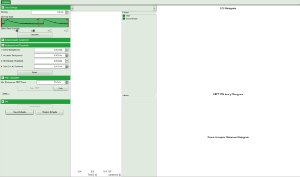
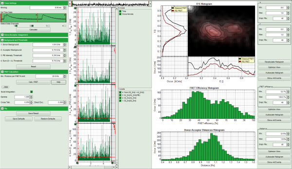
Note: The window contains three different regions:
- Left: Fitting and analysis options
- Center: Time traces. As the time traces are not yet calculated, this graph is still empty.
- Right: FRET distribution histogram and the FRET radius histogram. As these distributions have not been calculated yet, this area is still empty.
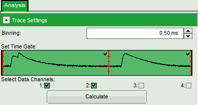
- In the “Trace Settings” on the left, change the binning to 0.5 ms.
Note: If you are unsure which binning to select, calculate the FCS curve and check the diffusion time to see the average residence time of the sample in the laser focus.
- Leave the other parameters of the “Trace Settings” unchanged and press “Calculate”.
Note:
Two channels need to be active in order to calculate spectral ratios.
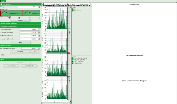
The data in this file are obtained under PIE (Pulsed Interleaved Excitation) conditions, which is visualized in the “Set Time Gate” area. In this example first a 530 nm pulse excited the Cy3 dye and consequently, the fluorescence of Cy3 and Cy5 - mainly excited via FRET - was detected in the two different channels. In this trace, donor and acceptor channel were recorded with a slight time delay, therefore two peaks can be seen in this area. This region is used to calculate the FRET efficiency histogram. The second area shows the fluorescence response after the second pulse (at 635 nm), which was used to excite the Cy5 dye directly. This information is used to distinguish molecules with and without acceptor dyes and to filter the events for signals without acceptor to calculate the stoichiometry parameter (see below). Both areas are automatically recognized and separated with a red bar.
Response:
- Four time traces are calculated and appear in the counter part of the window. The upper graph is automatically assigned to the donor channel after donor excitation (detector 2). The second graph shows the acceptor trace after donor excitation – automatically assigned to channel 1. The third graph shows the acceptor trace after acceptor excitation, and the last graph shows the trace generated using the sum of trace 1 and trace 2.
- The assignment of the detectors and the excitation pattern is shown when opening the “Donor/Acceptor Assignment” pull down menu. If this assignment is wrong, just invert it. In this case, the traces are automatically adapted.
- For the donor and acceptor traces, automatically the background counts are calculated. In the third trace automatically an intensity threshold is calculated for filtering out events without acceptor present. Four the fourth trace, also an intensity threshold is calculated, which is used in the calculation of the FRET histogram later. These values are drawn as green and red lines, respectively, in the graphs and can be manually adapted in the “Background and Thresholds” pull down menu.
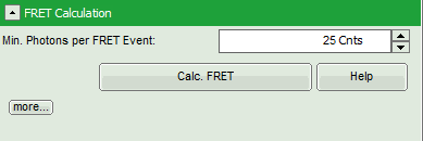
- Click on the “more…” button of the “FRET Calculation” pull down menu.
⇓
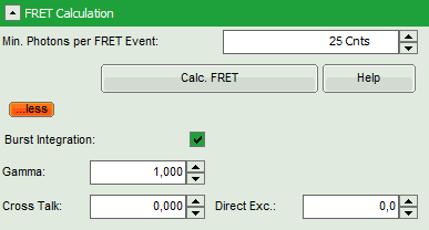
Response: Additional parameters are displayed.
- Enter the correct parameters for “Gamma”, “Cross Talk” and “Direct Exc.” for the system.
Note:
The check box “burst integration” should be checked for measurements of freely diffusing single molecules as in this example file. For observing conformational fluctuations of a single immobilized molecule, an analysis of the time bins set in the “Trace Settings” is appropriate. In that case, just deactivate the “Burst Integration” check box.
The “Cross Talk” can be determined measuring a solution containing only the donor dye to check which percentage leaks into the acceptor channel.
The “Direct Ext.” parameter is determined by exciting a solution containing only the acceptor with just the laser line normally used to excite the donor.
“Gamma” corrects for the different detection efficiencies in the donor and the acceptor channel, influences e.g. by detector quantum efficiency as well as filter sets.
The equations used for the FRET calculations and an explanation of the parameters can be found when clicking on the “Help” button.
- Click “Calc. FRET”.
Note: The parameter “Min. Photons per FRET Event” is by default set to 25. In order to calculate distinct FRET efficiencies, a much lower parameter does not make sense, as the possible values for the FRET efficiencies are otherwise too much determined by the photon numbers of the event. For example, in a burst with just 10 photons, only 11 FRET values are numerically possible, which is quite rough.
Response:
- The FRET efficiencies are calculated, The E/S-histogram graph is plotted, and the “FRET Efficiency” and “Donor-Acceptor Distances” histograms are drawn in the lower part of the image.
Note: These values are only correct, if the correct parameters for spectral bleed-through, direct excitation and channel sensitivity have been determined and entered into the script.
- In the 2D E/S-histogram, on the x - axis the frequency of events with a certain FRET efficiency is plotted, while on the y – axis, the frequency of events with a certain stoichiometry parameter S is shown.
- The stoichiometry parameter S is an indicator for the ratio of donor and acceptor dye. A ratio of 1 means that no acceptor molecule is present in these events, a S value of 0.5 indicates a ratio of 1:1 donor to acceptor.
- The E/S-histogram shows three discrete peaks. The first peak with low FRET intensity originates fromdonor only molecules (which were only labeled with the donor dye or where the acceptor had been photo-bleached), as clearly indicated by a S value of ~1. The other two peaks are due to twodifferent conformations of the RNA oligonucleotide measured in this sample.
- In the projections on the side and bottom of the “E/S Histogram”, the distribution of events without (“Classical FRET”) and with PIE based photon filtering (“PIE-FRET”) are plotted.
- Below the “E/S Histogram”, the FRET efficiency histogram is plotted again including PIE filtering.
- At the bottom, the distance histogram gives the distance of donor and acceptor dye in terms of “R0”, the Förster distance. To transfer this into a nanometer scale, the Förster distance must be known. Check standard textbooks like: J. Lakowicz, Principles of Fluorescence Spectroscopy, Springer about how to calculate the Förster distance and what artifacts are involved.
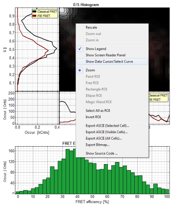
- If the FRET efficiencies of the two peaks should be indicated, place the mouse cursor over the graph, activate the context menu by a right mouse click and select “Show Data Reader/Select Curve”.
- Now place the mouse cursor over the peaks and read the FRET efficiency.
Note: In a similar fashion, also the values can be red from the E/S-Histogram. The context menu also has options for exporting the data as bitmap graph or in ASCII format.
- Store the result file by selecting: “Save Results”.
Response: A result file (PIE_FRET_TimeTrace_1.pqres) is stored under the raw data file (Cy3+Cy5_diff_PIE-FRET.ptu).
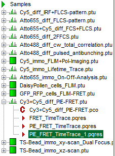
- Later, clicking on the result file reopens the file in the same way as it was stored.
- Now the necessary steps are finished, supposed the histograms were calculated with the correct parameters. They can be permanently registered in the script in the following way.
Permanently Store Calculation Parameters for Calculating the FRET Script
Note: Here it is assumed that parameters for calculation of the FRET traces have been adapted to the stored file and some changes regarding the default parameters have been necessary.
- Open the newly generated analysis file (if it was closed before).
- If the parameters should be used automatically also for procession of other files, click “File” → “Save Defaults”.
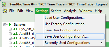
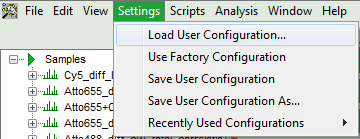
- Now, in the main menu, select “Settings\Save User Configuration as…”.
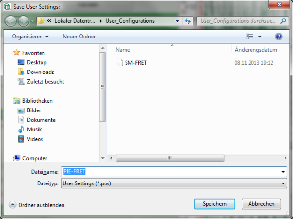
Response: A window pops up asking for a file name and a place to store the user configuration.
Note: Usually, when a system is delivered, a folder “C:\User_Configurations” is already present on the hard disc. If not, create it and save your profile there.
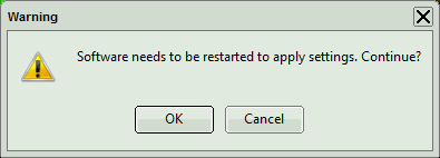
Response: A window pops up with the message that the software needs to be restarted to apply changes. Press OK.
Response: Software restarts, but applies the user profile PIE-FRET.pus.
- If the script is applied the next time to any file, the newly defined parameters will be used.
- Enter a name for the user configuration and press “Save”.
Response: The new user settings are saved under the given name as a file.
- To activate the user profile, go to “Settings\Load User Configuration”.
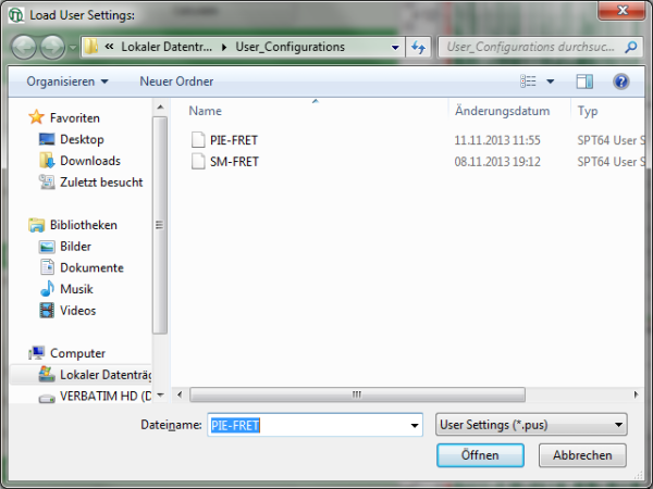
Response: A window opens to select the user settings file. Select the recently stored file.
Response: A window pops up with the message that the software needs to be restarted to apply changes. Press OK.

Response: Software restarts, but applies the user profile PIE-FRET.pus.
- If the script is applied the next time to any file, the newly defined parameters will be used.
Note: Further information about the sample used in this measurement can be found under: J.L. Fiore et. al., Enthalpy-driven RNA-folding: single-molecule thermodynamics of tetraloop-receptor tertiary interaction, Biochemistry (2009), 48(11), 2550-8. (http://pubs.acs.org/doi/abs/10.1021/bi8019788).
